


Diaphragm compressor
Date: May 27, 2024
By: Anhui Shengnuo Compressor Manufacturing Co.,Ltd
Classified by working principle
| Volumetric formula | Reciprocating | Piston type |
| Diaphragm type | ||
| Inclined plate type | ||
| Free piston type | ||
| Rotary | Screw type | |
| Roots equation | ||
| Liquid ring type | ||
| Slide type | ||
| Rotary piston type | ||
| Fluid dynamic type | Turbine type | Centrifugal type |
| Axial flow type | ||
| Mixed flow type | ||
| Jet type |
Classification by piston compression action
1) Single acting compressor: Gas is compressed only on one side of the piston, also known as a single acting compressor.
2) Double acting compressor: Gas can be compressed on both sides of the piston, also known as compound or multi acting compressor.
3) Multi cylinder single acting compressor: a compressor with multiple cylinders that uses one side of the piston for compression.
4) Multi cylinder double acting compressor: a compressor with multiple cylinders that utilizes both sides of the piston for compression.
Classified by the final exhaust pressure of the compressor
1) Low pressure compressor: The final exhaust pressure is 3-10Kg gauge pressure.
2) Medium pressure compressor: The final exhaust pressure is between 10-100Kg gauge pressure.
3) High pressure compressor: The final exhaust pressure is between 100-1000Kg gauge pressure.
4) Ultra high pressure compressor: The final exhaust pressure is above 1000Kg gauge pressure.
Classified by exhaust volume (import status)
| Type | Exhaust volume m ³/min |
| Micro compressor | <1 |
| Small compressor | 1-10 |
| Medium compressor | 10-60 |
| Large compressor | >60 |
Classified by structural form
It can be divided into vertical, horizontal, angular, symmetrical balanced, and opposed types. Generally used for small and medium-sized vertical applications; Horizontal for small high-voltage applications; Angle type is used for small and medium-sized; Symmetric balance type is widely used, especially in large and medium-sized reciprocating compressors; The standard is mainly used for ultra-high pressure compressors.
The meaning of the general structural code for reciprocating compressors in China is as follows: vertical - Z. Horizontal - P, angle - L S, Star shaped - T V、W、X, Symmetric equilibrium type - H M、D, Standard DZ.

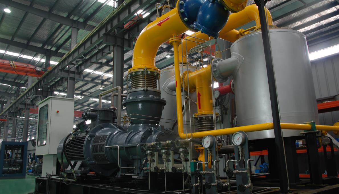
What is a diaphragm compressor?
The diaphragm compressor is named after its specially designed diaphragm, which separates the compressed gas from the outside world. Also known as "membrane compressor". In a diaphragm compressor, the function of the cylinder is accomplished by a diaphragm chamber, which is a cavity composed of a cylinder head with a dome shaped surface and an elastic diaphragm. The periphery of the diaphragm is tightly sealed between the cylinder head and the oil distribution plate. When the diaphragm is flexed and deformed by oil pressure, the volume in the diaphragm chamber changes accordingly. Thus, the pressure is transmitted to the gas in the membrane cavity, causing it to be compressed.
Difference between diaphragm compressor and reciprocating plug compressor
Formally:
Compared to piston engines, their similarity lies in that they are both volumetric compressors, which achieve the purpose of compressing gas through changes in volume; The main difference between the two is that the piston engine compresses gas through the volume change of the cavity composed of the piston and the cylinder, while the diaphragm engine compresses gas through the volume change of the membrane cavity, as mentioned above.
Performance wise:
1. Membrane compressors are suitable for larger compression ratios because the surface area of the compressed gas chamber is larger than the contact surface area of the gas volume, resulting in good heat dissipation performance. Therefore, a larger compression ratio can be selected. The compression ratio of membrane compressors is generally around 15, and sometimes it can reach around 25, so fewer stages can be used to obtain larger pressure; The compression ratio of reciprocating piston compressors is generally between 2-4, and the compression ratio of small and micro compressors can reach 6-8 under good cooling conditions, while the compression ratio of circulating compressors is generally between 1.1-1.3.
2. The characteristics of a membrane press are: high compression ratio, very high exhaust pressure, excellent airtightness, strong corrosion resistance, and small volumetric flow rate.
3. Requirements for metal membrane materials: high elasticity, high strength, fatigue resistance, and corrosion resistance.
4. Due to the fact that the operation of the membrane press is completed by the back and forth bending (deflection deformation) of the membrane, the deflection deformation of the membrane is limited by the temperature and fatigue properties of the membrane material. Therefore, the membrane cannot undergo transitional deflection. To reduce the transitional deflection of the membrane and improve its working life, it is necessary to increase the diameter of the cylinder head. The cylinder head is also limited to a certain extent by the source of the membrane material, so the exhaust volume of the membrane press is limited. The maximum exhaust volume of a single cylinder under atmospheric pressure intake is within 50m3/h.
General safety requirements for diaphragm compressors
General safety requirements
1. The operators of the membrane press must undergo formal training, be familiar with the structure, working principle, and user manual of the membrane press, and be able to correctly grasp the operation methods and safety measures before they can start working.
2. Do not easily start the membrane compressor without careful safety checks.
Any violation of safety regulations may result in equipment damage or endanger personal safety.
Before modifying any part of the compressor system, it is necessary to contact the design department of the manufacturer in advance.
Safety requirements for compressed parts
1. The buffer tank, intercooler, gas-liquid separator, and gas storage tank in the compressor gas circuit system are all pressure components. For pressure vessels, users should contact the local labor department and accept supervision before installation.
2. Safety valves and accessories should be properly maintained and regularly calibrated.
3. It is strictly prohibited for the compressor to run over temperature and pressure.
4. When the compressor is in operation or there is pressure in the system, do not tighten bolts or disassemble compressed parts (including crankcase plugs, covers, etc.).
Fire and explosion prevention requirements
1. For compressors that compress flammable, explosive or toxic gases, their installation, use, and operation should comply with relevant regulations.
Before introducing flammable gases, it is necessary to conduct an airtightness test and also replace the compressor system with nitrogen or other inert gases.
3. There should be anti toxic gas leakage measures in the factory building, and external discharge outlets (safety valve release outlet, cooler discharge outlet, etc.) in the gas circuit system should be connected with conduits to lead to outdoor safety zones or gas gathering for recovery.
4. Electrical equipment should meet the explosion-proof level required for compressed media.
Lubricating oil requirements
According to the compression medium of the membrane press, select lubricating oil for the membrane press, including oxygen, laughing gas, fluorinated gas, and media that react chemically with ordinary lubricating oil. Use 4838 and 4839 anti chemical lubricating oil or VPF1506XP lubricating oil. For general media, use anti-wear hydraulic oil. Choose YA-N46 in summer and YA-N32 in winter. Low temperature hydraulic oil can be selected in high-altitude cold areas, and its quality should comply with standard regulations. Different types of lubricating oil should not be mixed. Lubricating oil should be replaced regularly.
Cooling water requirements
The cooling water should be kept clean to prevent scaling in the waterproof channel.
The cooling water quality requirements are:
1. Organic and mechanical impurities and suspended solids should be less than 100mg/L, and oil content should be less than 5mg/L;
2. Near neutral, with a pH value of 6.5-9;
3. It has thermal stability and a temporary hardness of less than 10 degrees (hardness of 1 ° is equivalent to 1L of water, containing 10mg of Cao or 1gmgr of Mgo);
Personal protection requirements
1. During the operation of the compressor, personal or clothing should not come into contact with moving parts such as transmission belts, chains, couplings, fans, etc.
2. Do not touch the cylinder head and exhaust pipes to avoid burns.
Electrical requirements
1. The installation and maintenance of electrical equipment for the membrane press should comply with relevant regulations on electrical safety.
2. The operator must hold the corresponding electrician operation qualification certificate and work under the guidance of electrical technicians. Before repairing the electrical equipment, the power should be cut off, and there should be a dedicated person to monitor and warning signs.
The basic structure and working principle of diaphragm compressors
The body and moving parts of the membrane compressor are basically the same as the structural principle of the reciprocating piston compressor. The difference between them is that the piston of the membrane compressor does not come into contact with the compressed medium, while the piston of the piston compressor directly comes into contact with the compressed medium. So it is called a diaphragm compressor.
The cylinder head and the supporting orifice plate(oil distribution plate) are machined with special curved surfaces on their end faces, and the periphery of the metal diaphragm is tightly clamped in their middle, thus being divided into an air chamber and an oil chamber; Air chamber - the spatial structure contained between the curved surface of the cylinder head and the diaphragm, while oil chamber - is composed of the space contained between the top of the piston and the diaphragm; The crank connecting rod mechanism drives the piston to move back and forth, periodically changing the oil pressure in the oil chamber. High pressure oil pushes the diaphragm, forcing it to fold with the frequency of piston reciprocating motion, changing the volume of the air chamber. With the cooperation of the inlet and outlet valves, four processes are achieved: expansion - intake - compression - exhaust, completing one cycle process. In order to ensure that all the gas in the gas chamber can be discharged in each cycle (except for reasonable residual gas), the diaphragm must be completely attached to the cylinder head surface every time. Therefore, the oil pressure must be higher than the exhaust pressure by a certain value. Generally, the oil discharge pressure should be 5-15% higher than the exhaust pressure and should not be less than 1.5kg/cm2. To meet this requirement, a plunger type compensating oil pump is installed at one end of the crankshaft. After each cycle is completed, a certain amount of oil is promptly flushed into and out of the oil chamber. The amount of compensating oil should be slightly more than the amount of oil leakage around the piston and the amount of oil compression, so as to ensure the normal operation of the membrane compressor. The oil pressure in the oil chamber is controlled by a spring type oil pressure control valve (pressure regulating valve or gas-liquid follow-up valve) set on the oil chamber, ensuring that the pressure of each oil discharge is within the specified range to ensure the normal operation of the membrane compressor.
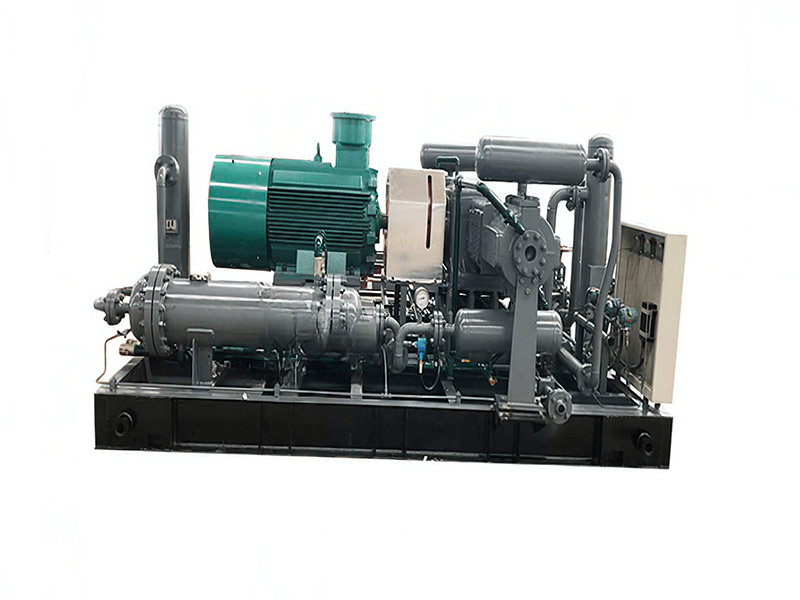
Taking the G3V-20/200 diaphragm compressor as an example, this article provides a detailed introduction to the structure of each component, its function on the machine, and maintenance precautions.
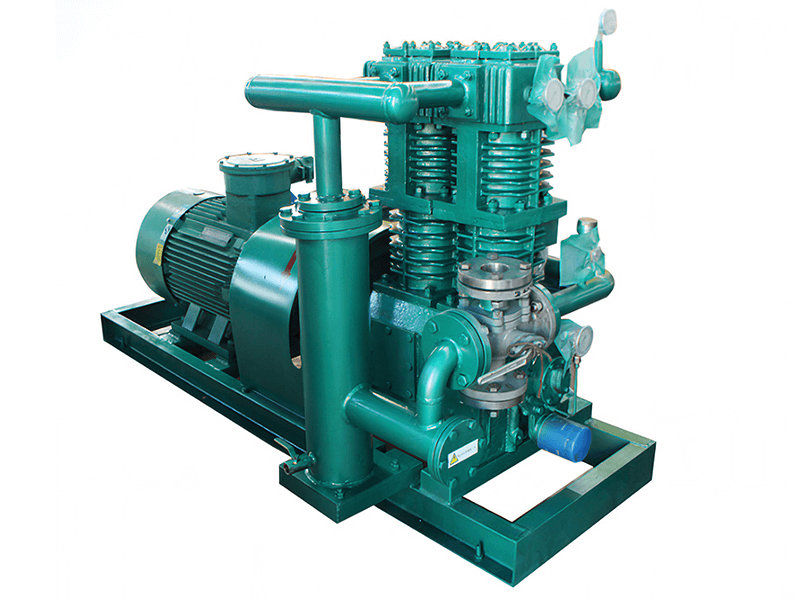
G3V-20/1-200 diaphragm compressor
1. Overview of purpose and overall structure:
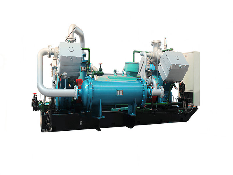
Diaphragm compressor is a special type of compressor with no friction or lubrication in the air chamber (cylinder). The compressed gas does not come into contact with any lubricant and has excellent sealing performance. Therefore, it is particularly suitable for compressing and conveying high-purity, rare gases, toxic, explosive, and corrosive gases. This type of machine can operate from very low pressure up to 2000kgf/cm2 (there are already prototypes with pressures as high as 7000kgf/cm2 in international laboratories), so it is an indispensable equipment in the petrochemical industry, atomic energy industry, air separation industry, military industry, scientific research and other units.
2. Main structural type, main components, and main technical parameters of the host:
The host is a V-shaped structure, with secondary compression, water cooling, rolling bearings, splash lubrication, electric motor drive, V-belt drive, piston stroke of 130mm, and crankshaft speed generally controlled at around 400r/min.
Main components of the host
The components include the crankcase assembly, crankshaft connecting rod piston assembly, cylinder body assembly, transmission assembly, compensation oil pump oil circuit assembly system, and air water pipeline system.
Main technical performance indicator
Compressed medium: air
Exhaust volume: 20m3/h
First stage suction and exhaust pressure: px1=0 (gauge pressure) ph1=11~13kgf/cm2
Secondary suction and exhaust pressure: px2=11~13kgf/cm2 ph2=200kgf/cm2
Fixed value of interstage safety valve: 14.5-15kgf/cm2
Control values for various combinations of G3V-20/200 diaphragm compressor during final assembly
1. During the final assembly, the axial clearance of the crankshaft should be 0.3-0.5mm, as the temperature of the compressor will increase during operation (generally ≤ 65 ° C) to prevent thermal expansion during crankshaft operation, which may affect normal operation.
2. To prevent oil leakage, a thin layer of varnish should be applied to the distribution surface of the crankcase before tightening.
3. The rolling bearings of the crankshaft housing are fitted in a transitional fit. The centerline of the two bearing holes should be parallel to the box surface with a tolerance of less than 0.2mm. The coaxiality tolerance of the two bearing holes is less than 0.01mm.
4. Before machining the bearing holes in the box, two 1:50 taper pins must be installed to ensure the accuracy of each position of the box.
5. The smoothness of the tapered hole of the large pulley is ▽ 6, and it should be inspected by coloring with a standard cone plug gauge. The contact area should not be less than 50% and should be evenly distributed. After processing the finished product of the belt pulley, a static balance test should be conducted, with a weight deviation of less than 20g allowed to ensure balanced operation.
6. In the assembly of the cylinder body, the gap between the lower support foot of the oil distribution plate and the support foot of the cylinder body should be 0.1 ± 0.05mm.
When tightening the bolts around the cylinder head and cylinder block, they should be gradually tightened diagonally and evenly (tightening force can be divided into four times: 30% force for the first time, 60% force for the second time, 85-90% force for the third time, and 100% force for the fourth time). No oil leakage is allowed during work.
7. Burrs are not allowed on the holes of the oil distribution plate and cylinder head, but large corners are also not allowed.
8. The outer diameter of the piston should be perpendicular to the centerline of the pin hole with a tolerance of 0.02/100mm, and the non intersection tolerance should be 0.15mm. The two ends of the piston ring groove should be perpendicular to the outer diameter with a tolerance of 0.05/100mm.
9. The allowable deviation between the two end journals of the crankshaft and the two center lines of the crankshaft is 0.02/100mm. The allowable deviation of runout between the two end journals and the tapered journal of the flywheel installation is 0.03mm. The color inspection of the taper surface should not be less than 50% and the contact should be uniform.
10. The parallelism tolerance between the large and small end holes of the connecting rod is 0.02mm.
11. The allowable deviation between the outer diameter of the crosshead and the verticality of the pin hole is 0.02/100mm. The tolerance for parallelism between the pin hole and the top surface is 0.02/100mm. The axial clearance between the piston rod head flange and the gasket ring is 0.04-0.10mm.
12. Gap between piston ring openings:
Delta=σ π D (t1-t2) mm
In the formula: D cylinder diameter (mm)
t1 The ambient temperature for detecting delta is usually taken as room temperature (0C)
t2 The working temperature of the piston ring is usually taken as the exhaust temperature (0C)
σ Linear expansion coefficient of piston ring material (1/0C)
Cast iron σ =1.1x10⁻⁵/0C
Fill in F4 σ =3~5x10⁻⁵/0C
Nylon 6 σ=9~11x10-5/0C
Aluminum alloy σ=2.3x10⁻⁵/0C

 Apr 27, 2024